So eds. What is the electromotive force emf. Definition and physical meaning
In the midst school year many scientists required emf formula for different calculations. Experiments related to also need information about the electromotive force. But for beginners, it is not so easy to understand what it is.
The formula for finding emf
Let's deal with the definition first. What does this abbreviation mean?
EMF or electromotive force is a parameter characterizing the work of any forces of a non-electric nature operating in circuits where the current strength, both direct and alternating, is the same along the entire length. In a coupled conductive circuit, the EMF is equated to the work of these forces in moving a single positive (positive) charge along the entire circuit.
The figure below shows the emf formula.
Ast - means the work of external forces in joules.
q is the transferred charge in coulombs.
Third party forces- these are the forces that carry out the separation of charges in the source and, as a result, form a potential difference at its poles.
For this force, the unit of measure is volt. It is denoted in the formulas by the letter « E".
Only at the moment of the absence of current in the battery, the electromotive si-a will be equal to the voltage at the poles.
EMF induction:

EMF of induction in a circuit havingNturns:

When driving:

Electromotive force induction in a circuit rotating in a magnetic field at a speedw:

Table of values

A simple explanation of the electromotive force
Suppose there is a water tower in our village. It is completely filled with water. Let's think that this is an ordinary battery. The tower is a battery!
All the water will put a lot of pressure on the bottom of our turret. But it will be strong only when this structure is completely filled with H 2 O.
As a result, the less water, the weaker the pressure will be and the pressure of the jet will be less. Opening the tap, we note that every minute the jet range will be reduced.
As a result:
- Tension is the force with which the water presses on the bottom. That is pressure.
- Zero voltage is the bottom of the tower.
The battery is the same.
First of all, we connect a source of energy to the circuit. And we close it accordingly. For example, insert a battery into a flashlight and turn it on. Initially, note that the device is lit brightly. After a while, its brightness will noticeably decrease. That is, the electromotive force has decreased (leaked when compared with water in the tower).
If we take a water tower as an example, then the EMF is a pump that constantly pumps water into the tower. And it never ends there.
EMF of a galvanic cell - formula
The electromotive force of a battery can be calculated in two ways:
- Perform the calculation using the Nernst equation. It will be necessary to calculate the electrode potentials of each electrode included in the GE. Then calculate the EMF using the formula.
- Calculate the EMF using the Nernst formula for the total current generating the reaction that occurs during the operation of the GE.

Thus, armed with these formulas, it will be easier to calculate the electromotive force of the battery.
Where are different types of EMF used?
- Piezoelectric is used when a material is stretched or compressed. With the help of it, quartz energy generators and various sensors are made.
- Chemical is used in and batteries.
- Induction appears at the moment the conductor crosses magnetic field. Its properties are used in transformers, electric motors, generators.
- Thermoelectric is formed at the moment of heating contacts of different types of metals. It has found its application in refrigeration units and thermocouples.
- Photo electric is used to produce photovoltaic cells.
Electromotive Force (EMF)- in a device that performs forced separation of positive and negative charges (generator), a value numerically equal to the potential difference between the generator terminals in the absence of current in its circuit is measured in Volts.
Sources of electromagnetic energy (generators)- devices that convert energy of any non-electric form into electrical energy. Such sources are, for example:
generators at power plants (thermal, wind, nuclear, hydroelectric power plants) that convert mechanical energy into electrical energy;
galvanic cells (batteries) and accumulators of all types that convert chemical energy into electrical energy, etc.
EMF is numerically equal to the work that external forces do when moving a unit positive charge inside the source or the source itself, conducting a unit positive charge through a closed circuit.
The electromotive force EMF E is a scalar quantity that characterizes the ability of an external field and an induced electric field to induce an electric current. EMF E is numerically equal to the work (energy) W in joules (J) expended by this field to move a unit of charge (1 C) from one point of the field to another.
The unit of measure for EMF is the volt (V). Thus, the EMF is equal to 1 V if, when a charge of 1 C is moved along a closed circuit, work of 1 J is performed: [E] = I J / 1 C = 1 V.
The movement of charges around the site is accompanied by the expenditure of energy.
The value numerically equal to the work done by the source, conducting a single positive charge through a given section of the circuit, is called voltage U. Since the circuit consists of external and internal sections, the concepts of voltages in the external Uin and internal Uvt sections are distinguished.
From what has been said, it is obvious that The EMF of the source is equal to the sum of the voltages on the external U and internal U sections of the circuit:
E \u003d Uvsh + Uvt.
This formula expresses the law of conservation of energy for an electrical circuit.
It is possible to measure voltages in various parts of the circuit only when the circuit is closed. EMF is measured between the source terminals with an open circuit.

The direction of the EMF is the direction of the forced movement of positive charges inside the generator from minus to plus under the action of a nature other than electrical.
The internal resistance of the generator is the resistance of the structural elements inside it.
Ideal EMF source- a generator, which is equal to zero, and the voltage at its terminals does not depend on the load. The power of an ideal EMF source is infinite.
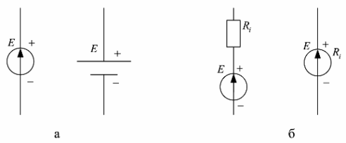
Conditional image (electric circuit) of an ideal EMF generator with a value of E shown in fig. 1, a.
A real EMF source, unlike an ideal one, contains an internal resistance Ri and its voltage depends on the load (Fig. 1., b), and the source power is finite. The electrical circuit of a real EMF generator is a series connection of an ideal EMF generator E and its internal resistance Ri.
In practice, in order to bring the operating mode of a real EMF generator closer to the ideal operating mode, they try to make the internal resistance of a real generator Ri as small as possible, and the load resistance Rn must be connected with a value of at least 10 times greater than the internal resistance of the generator , i.e. condition must be met: Rn >> Ri
In order for the output voltage of a real EMF generator not to depend on the load, it is stabilized using special electronic voltage stabilization circuits.
Since the internal resistance of a real EMF generator cannot be made infinitely small, it is minimized and performed as a standard for the possibility of a consistent connection of energy consumers to it. In radio engineering, the standard output impedance of EMF generators is 50 ohms (industrial standard) and 75 ohms (household standard).
For example, all television receivers have an input impedance of 75 ohms and are connected to the antennas with a coaxial cable of just such a wave impedance.
To approach ideal EMF generators, the supply voltage sources used in all industrial and household radio-electronic equipment are performed using special electronic output voltage stabilization circuits that allow you to maintain an almost constant output voltage of the power source in a given range of currents consumed from the EMF source (sometimes it called a voltage source).
On electrical circuits, EMF sources are depicted as follows: E - a source of constant EMF, e (t) - a source of harmonic (variable) EMF in the form of a function of time.
The electromotive force E of a battery of identical cells connected in series is equal to the electromotive force of one cell E multiplied by the number of cells n of the battery: E = nE.
The electromotive force, in the people of EMF, as well as the voltage is measured in volts, but is of a completely different nature.
EMF in terms of hydraulics
I think you are already familiar with the water tower from the last article about
Assume that the tower is completely filled with water. We drilled a hole at the bottom of the tower and cut a pipe into it, through which water runs to your house.

The neighbor wanted to water the cucumbers, you decided to wash the car, the mother started the laundry and voila! The flow of water became less and less, and soon completely dried up ... What happened? The tower ran out of water...

The time it takes to empty the tower depends on the capacity of the tower itself, as well as how many consumers will use the water.
All the same can be said about the radio element capacitor:

Let's say we charged it from a 1.5 volt battery and it took a charge. Let's draw a charged capacitor like this:

But as soon as we connect a load to it (let the LED be the load) by closing the key S, in the first fraction of seconds the LED will glow brightly, and then fade away quietly ... and until it goes out completely. The extinction time of the LED will depend on the capacitance of the capacitor, as well as on what load we attach to the charged capacitor.

As I said, this is tantamount to a simple filled tower and consumers who use water.
But why then does our towers never run out of water? Yes because it works. water supply pump! Where does this pump get its water from? From a well that was drilled to extract groundwater. Sometimes it is also called artesian.

As soon as the tower is completely filled with water, the pump turns off. In our water towers, the pump always maintains the maximum water level.
So, let's remember what is stress? By analogy with hydraulics, this is the water level in the water tower. A full tower is the maximum water level, which means the maximum voltage. No water in the tower - zero voltage.
EMF of electric current
As you remember from previous articles, water molecules are “electrons”. For the emergence electric current, the electrons must move in the same direction. But for them to move in the same direction, there must be tension and some kind of load. That is, the water in the tower is a tension, and the people who spend water for their needs are a burden, since they create a flow of water from a pipe located at the foot of the tower. And the flow is nothing but the strength of the current.
The condition must also be observed that the water must always be at the maximum level, regardless of how many people spend it for their needs at the same time, otherwise the tower will be empty. For a water tower, this life-saving tool is a water pump. What about electric current?
For an electric current, there must be some kind of force that would push the electrons in one direction for a long time. That is, this force must move the electrons! Electromotive force! Yes exactly! ELECTROMOTIVE FORCE! You can call it abbreviated EMF - E electro D seeing WITH silt. It is measured in volts, like voltage, and is indicated mainly by the letter E.
Does this mean that our batteries also have such a “pump”? There is, and it would be more correct to call it “electron pump”). But, of course, no one says that. They simply say - EMF. I wonder where this pump is hidden in the battery? This is simply an electrochemical reaction, due to which the “water level” in the battery is kept, but then, nevertheless, this pump wears out and the voltage in the battery begins to sag, because the “pump” does not have time to pump water. In the end, it completely breaks down and the voltage on the battery drops to almost zero.
Real EMF source
The source of electrical energy is a source of EMF with internal resistance R ext. It could be any chemical elements power supplies such as batteries and accumulators

Their internal structure in terms of EMF looks something like this:

Where E is the EMF, and R ext is the internal resistance of the battery
So what conclusions can be drawn from this?
If no load clings to the battery, such as an incandescent lamp, etc., then as a result, the current strength in such a circuit will be zero. A simplified diagram would be:

But if we nevertheless attach an incandescent bulb to our battery, then our circuit will become closed and current will flow in the circuit:

If you draw a graph of the dependence of the strength in the current circuit on the voltage on the battery, then it will look like this:

What is the conclusion? In order to measure the EMF of a battery, we just need to take a good multimeter with a high input resistance and measure the voltage at the battery terminals.
Ideal EMF source
Let's say that our battery has zero internal resistance, then it turns out that R ext \u003d 0.
It is easy to guess that in this case the voltage drop across zero resistance will also be zero. As a result, our graph will look like this:

As a result, we got just an EMF source. Therefore, an EMF source is an ideal power source, in which the voltage at the terminals does not depend on the strength of the current in the circuit. That is, no matter what load we would attach to such an EMF source, in our case it will still give out the required voltage without a drawdown. The EMF source itself is designated as follows:

In practice, there is no ideal source of emf.
EMF types
– electrochemical(EMF of batteries and accumulators)
– photoelectric effect(receiving electric current from solar energy)
– induction(generators using the principle of electromagnetic induction)
– Seebeck effect or thermoEMF(the occurrence of an electric current in a closed circuit consisting of series-connected dissimilar conductors, the contacts between which are at various temperatures)
– piezoEMF(receiving EMF from )
Summary
EMF is a non-electrical force that causes an electric current to flow in a circuit.
Real The EMF source has an internal resistance inside it. ideal EMF source internal resistance is zero.
An ideal EMF source always has a constant voltage value at its terminals, regardless of the load in the circuit.
Content:
When the concept of "electron" was born, people immediately associated it with a certain job. Electron is Greek for amber. The fact that the Greeks, in order to find this useless, in general, magical stone, had to travel quite far to the north - such efforts here, in general, do not count. But it was worth doing some work - by rubbing a pebble on a dry woolen cloth with your hands - and it acquired new properties. Everyone knew it. To rub just like that, for the sake of a purely disinterested interest, in order to observe how now small debris begins to be attracted to the “electron”: dust particles, hairs, threads, feathers. In the future, when a whole class of phenomena appeared, later united in the concept of "electricity", the work that must be spent without fail did not give people peace. Since you need to spend it to get a trick with dust particles, it means that it would be nice to somehow save this work, accumulate it, and then get it back.
Thus, from more and more complicated tricks with different materials and philosophical reasoning, they learned to collect this magical power in a jar. And then make it so that it is gradually released from the jar, causing actions that can already be felt, and very soon measured. And they measured it so ingeniously, having just a couple of silk balls or sticks and spring torsion balances, that even now we quite seriously use all the same formulas for calculating electrical circuits that have now permeated the entire planet, infinitely complex, compared with those first devices. .

And the name of this mighty genie, sitting in a jar, still contains the delight of old discoverers: "Electromotive force." But this force is not electrical at all. On the contrary, an extraneous terrible force, forcing electric charges move "against their will", that is, overcoming mutual repulsion, and gather somewhere on one side. This results in a potential difference. It can also be used by launching charges in a different way. Where they are "not guarded" by this terrible EMF. And to force, thereby, to do some work.
Principle of operation
EMF is a force of a very different nature, although it is measured in volts:

- Chemical. It comes from the processes of chemical substitution of ions of some metals by ions of others (more active). As a result, extra electrons are formed, tending to "escape" at the edge of the nearest conductor. This process can be reversible or irreversible. Reversible - in batteries. They can be charged by returning the charged ions back into the solution, which makes it more acidic, for example (in acid batteries). The acidity of the electrolyte is the reason for the EMF of the battery, it works continuously until the solution becomes absolutely chemically neutral.


- Magnetodynamic. Occurs when a conductor, in some way oriented in space, is exposed to a changing magnetic field. Or from a magnet moving relative to a conductor, or from the movement of a conductor relative to a magnetic field. Electrons in this case also tend to move in the conductor, which allows them to be captured and placed on the output contacts of the device, creating a potential difference.


- electromagnetic. An alternating magnetic field is created in the magnetic material by an alternating electrical voltage of the primary winding. In the secondary winding, the movement of electrons occurs, and hence the voltage is proportional to the voltage in the primary winding. The EMF symbol can be used to designate transformers in equivalent substitution circuits.

- Photovoltaic. Light, falling on some conductive materials, is able to knock out electrons, that is, to make them free. An excess of these particles is created, which is why the excess ones are pushed to one of the electrodes (anode). There is a voltage that can generate an electric current. Such devices are called photocells. Initially, vacuum photocells were invented, in which the electrodes were installed in a flask with a vacuum. In this case, the electrons were pushed out of the metal plate (cathode) and captured by another electrode (anode). Such photocells have found application in light sensors. With the invention of more practical semiconductor photocells, it became possible to create powerful batteries from them, in order to generate a significant voltage by summing the electromotive force of each of them.

- Thermoelectric. If two different metals or semiconductors are soldered at one point, and then heat is delivered to this point, for example, candles, then at the opposite ends of a pair of metals (thermocouples) there is a difference in the density of the electron gas. This difference can accumulate if thermocouples are connected in series, similar to the connection of galvanic cells in a battery or individual photovoltaic cells in a solar battery. ThermoEMF is used in very accurate temperature sensors. This phenomenon is associated with several effects (Peltier, Thomson, Seebeck), which are successfully investigated. It is a fact that heat can be directly converted into electromotive force, i.e. voltage.

- electrostatic. Such sources of EMF were invented almost simultaneously with galvanic cells or even earlier (if we consider rubbing amber with silk as a normal production of EMF). They are also called electrophore machines, or, after the name of the inventor, Wimshurst generators. Although Wimshurst created a clear technical solution that allows the removed potential to be accumulated in a Leiden jar - the first capacitor (moreover, of good capacity). The first electrophore machine can be considered a huge ball of sulfur, mounted on an axis, the apparatus of the Magdeburg burgomaster Otto von Guericke in the middle of the 17th century. The principle of operation is rubbing materials that are easily electrified from friction. True, von Guericke's progress can be called, as the saying goes, driven by laziness, when there is no desire to rub amber or something else by hand. Although, of course, this inquisitive politician of something, but fantasy and activity was not to be occupied. Let us recall at least his well-known experience with two strings of donkeys (or mules) tearing a ball without air by the chains into two hemispheres.

Electrization, as originally assumed, comes precisely from “friction”, that is, by rubbing amber with a rag, we “tear off” electrons from its surface. However, studies have shown that this is not so simple. It turns out that there are always charge irregularities on the surface of dielectrics, and ions from the air are attracted to these irregularities. Such an air-ion coat is formed, which we damage by rubbing the surface.
- Thermionic. When metals are heated, electrons are released from their surface. In a vacuum, they reach another electrode and induce a negative potential there. A very promising direction right now. The figure shows a scheme for protecting a hypersonic aircraft from overheating of body parts by an oncoming air flow, and the thermoelectrons emitted by the cathode (which is then cooled - the simultaneous action of the Peltier and / or Thomson effects) reach the anode, inducing a charge on it. The charge, or rather, the voltage, which is equal to the received EMF, can be used in the consumption circuit inside the device.

1 - cathode, 2 - anode, 3, 4 - cathode and anode taps, 5 - consumer
- Piezoelectric. Many crystalline dielectrics, when they experience mechanical pressure on themselves in any direction, react to it by inducing a potential difference between their surfaces. This difference depends on the applied pressure and is therefore already used in pressure sensors. Piezoelectric gas stove lighters do not require any other source of energy - just pressing a button with your finger. Known attempts to create a piezoelectric ignition system in vehicles based on piezoceramics, receiving pressure from a system of cams associated with the main shaft of the engine. "Good" piezoelectrics - in which the EMF proportionality to pressure is highly accurate - are very hard (for example, quartz), they almost do not deform under mechanical pressure.


- However, long exposure to pressure on them causes their destruction. In nature, thick layers of rock are also piezoelectric, the pressure of the earth's strata induces huge charges on their surfaces, which gives rise to titanic storms and thunderstorms in the depths of the earth. However, not everything is so terrible. Elastic piezoelectrics have already been developed, and even the manufacture of products based on them (and based on nanotechnology) for sale has already begun.
The fact that the unit of measurement of EMF is the unit of electrical voltage is understandable. Since the most diverse mechanisms that create the electromotive force of the current source all convert their types of energy into the movement and accumulation of electrons, and this ultimately leads to the appearance of such a voltage.
Current arising from EMF
The electromotive force of the current source is the driving force that the electrons from it begin to move if closed electrical circuit. EMF forces them to do this, using its non-electric "half" of nature, which does not depend, after all, on the half associated with electrons. Since it is believed that the current in the circuit flows from plus to minus (such a direction was determined before everyone knew that the electron is a negative particle), then inside the device with EMF, the current makes the final movement - from minus to plus. And they always draw at the EMF sign, where the arrow - + is directed. Only in both cases - both inside the EMF of the current source, and outside, that is, in the consuming circuit - we are dealing with electric current with all its mandatory properties. In conductors, current encounters their resistance. And here, in the first half of the cycle, we have the load resistance, in the second, internal, - the source resistance or internal resistance.
The internal process does not work instantly (although very quickly), but with a certain intensity. He does the work of delivering charges from minus to plus, and this also meets with resistance ...

Resistance is of two kinds.
- Internal resistance works against the forces separating the charges, it has a nature "close" to these separating forces. At least it works with them in a single mechanism. For example, an acid that takes oxygen from lead dioxide and replaces it with SO 4 - ions definitely experiences some chemical resistance. And this just manifests itself as the work of the internal resistance of the battery.
- When the outer (output) half of the circuit is not closed, the appearance of more and more electrons at one of the poles (and their decrease from the other pole) causes an increase in tension electrostatic field on the poles of the battery and an increase in repulsion between electrons. This allows the system to “not go haywire” and stop at a certain state of saturation. No more electrons from the battery are taken outside. And it outwardly looks like the presence of a constant electrical voltage between the battery terminals, which is called U xx, the open circuit voltage. And it is numerically equal to EMF - electromotive force. Therefore, the unit of measure for EMF is the volt (in the SI system).
But if you only connect a load of conductors with non-zero resistance to the battery, then a current will immediately flow, the strength of which is determined by Ohm's law.
It would seem that it is possible to measure the internal resistance of the EMF source. It is worth including an ammeter in the circuit and shunting (shorting) the external resistance. However, the internal resistance is so low that the battery will begin to discharge catastrophically, generating a huge amount of heat, both on the external shorted conductors and in the internal space of the source.
However, you can do it differently:
- Measure E (remember, open circuit voltage, the unit of measurement is volts).
- Connect some resistor as a load and measure the voltage drop across it. Calculate the current I 1 .
- You can calculate the value of the internal resistance of the EMF source using the expression for r

Typically, the ability of a battery to produce electricity is measured by its energy "capacity" in ampere hours. But it would be interesting to see what maximum current it can produce. Despite the fact that perhaps the electromotive force of the current source will cause it to explode. Since the idea to arrange a short circuit on it did not seem very tempting, this value can be calculated purely theoretically. EMF is equal to U xx. You just need to draw a graph of the voltage drop across the resistor versus current (and therefore the load resistance) to the point where the load resistance will be zero. This is the point Ikz, intersection of the red line with the coordinate line I , in which the voltage U has become zero, and the entire voltage E of the source will fall on the internal resistance.
Often seemingly simple basic concepts can not always be understood without examples and analogies. What is the electromotive force, and how it works, can only be imagined by considering its many manifestations. And it is worth considering the definition of EMF, as it is given by solid sources through clever academic words - and start all over from the beginning: the electromotive force of the current source. Or just print on the wall in gold letters:

Let us find out what value is the main characteristic of the current source. Any current source has two poles: positive and negative. In order for it to have these poles, it is necessary to collect free positive charges inside it at one pole, and negative charges at the other. To do this, you need to do work. This work cannot be done by electrostatic forces, since unlike charges are attracted, and they must be separated. The work on the accumulation of charges is carried out not by electrostatic forces, but by third parties. The nature of the latter may be different. For example, in electric current generators, the separation of charges is carried out by the forces of the magnetic field, in batteries and galvanic cells - by chemical ones. The study of current sources shows that the ratio of the work of an external force to the charge accumulated at the pole for a given current source is a constant value and is called the electromotive force of the current source:
Electromotive force of current source
The scalar value, which is a characteristic of the current source and measured by the work done by an external force inside it by accumulating 1 k of charge on each pole, is called the electromotive force of the current source. Charge in 1 to, accumulated at the pole of the current source, has a potential electrical energy numerically equal to e. d.s. source.
Unit e. d.s.

Let's measure e. d.s. current source. We connect a voltmeter to the demonstration galvanic cell (Fig. 75, a) *. By changing the relative position of the electrodes in the electrolyte, as well as the amount of their immersion in the electrolyte, we see that the readings of the voltmeter ( 1.02 in) do not change. E. d. s. does not depend on the size of the current source. It depends only on the nature of external forces causing the accumulation of charges at the poles. Each current source has its own e. d.s.
* (With such a freeze, d.s. the voltmeter reading will be slightly less than the e value. d.s. The greater the resistance of the voltmeter coil compared to the internal resistance of the source, the smaller this difference will be, which is observed in the described experiment.)
When the electrical circuit is closed, the current source forms a stationary electric field in the wires and transfers to it the energy accumulated by the charges on its poles. Due to this energy, the stationary field does work to form a current, transferring its energy to it, which the current consumer converts into other types of energy.
The internal part of the circuit that makes up the current source, like any conductor, has resistance; it's called internal resistance of the current source r. For a current generator, the internal resistance is the resistance of the armature winding, for chemical sources electrolyte resistance.
When the circuit is closed, the electric field, moving the charge 1 to from point A to point B along the outer section of the circuit (Fig. 75, b), performs work that is numerically equal to the voltage U in this section. Having reached the pole B, the charge 1 to must go to the inner section of the circuit and move to pole A. In order for it to be at pole A again and have the same energy E as when leaving point A, the external forces of the current source must do work on it equal to the work expended on it movement along the external section of the circuit, which is numerically equal to the voltage U in this section, plus the work expended on overcoming the internal resistance r of the source. The latter is numerically equal to the voltage u in the inner section of the circuit. Therefore, e. d.s. source is numerically equal to E \u003d U + u.The electromotive force is numerically equal to the work that the current source does by moving a charge of 1 k throughout the circuit.
We measure the voltage on the outer and inner sections; chains (Fig. 75, c) *. Voltmeter A shows the voltage on the external resistance R, and voltmeter B - on the internal; resistance r. By changing the value of the resistance of the external circuit; we notice that in this case, the voltage in the sections of the circuit changes (Table 4).
* (Probes 1 and 2 are made of thick copper wire in PVC insulation, which is cut off from the side located towards the middle of the vessel. The probes are in contact with the electrodes with insulation.)

We see that the sum of the voltages on the outer and inner sections of the circuit is a constant value (within the limits of experimental errors) and is equal to e. d.s. source. It shows the amount of energy that the current source is able to transfer to the electrical circuit when moving through the entire charge circuit in 1 to.